Common Relays (With Pics)

SSTJ

———
Lifetime Supporting Member
Joined
Aug 24, 2019
Messages
3,403
Location
South Carolina
I'm wiring some fogs, and realized that I still don't know the basics of relays. If others will help fill this in, I'll make a table that may be useful to others who come along. For example, I found what I think is a SPDT in my garage today, but cannot remember why I bought it, or when it would be helpful.

———

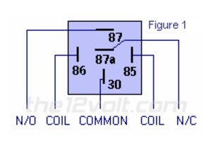
From @freedom_in_4low: A relay has a coil, and contacts. The switch supplies voltage across the coil (pins 85 and 86), and then the contacts change state. An animated illustration is provided by @Jerry Bransford here.

The table below gives some common examples, most of which is also explained here. Also, I learned here that relays like these only draw about 0.16 amps across the 85 and 86 pins.

Name
Pics
Diagram
Notes
Example
SinglePole,
SingleThrow

(SPST)


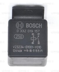
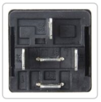
Screenshot 2024-01-01 at 7.34.06 PM.jpg

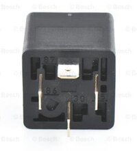
Screenshot 2024-01-01 at 7.34.11 PM.jpg


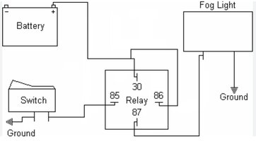
Screenshot 2024-01-01 at 9.26.10 PM.jpg
Most commonly used for an aftermarket accessory. Wiring aux lights, for instance.

As the name suggests, this offers only one "on" position for a single switch.

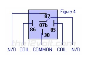
A typical SPST relay will have 2 pins for the contacts, which will be normally open (NO) which means the contacts will be open when the coil is not energized, and the contacts will close when coil is energized. These are pins 30 (common) and 87 (NO).
Bosch, via Summit

Bosch High_Amp

DualMake,
SinglePole,
SingleThrow

(SPST)

"Headlight"


Screenshot 2024-01-02 at 9.20.52 AM.jpg

Screenshot 2024-01-02 at 9.20.42 AM.jpg


Screenshot 2024-01-02 at 11.56.48 AM.jpg

Screenshot 2024-01-02 at 11.56.58 AM.jpg
These "Dual Make" SPSTs are like SPSTs, but instead of providing power to one pin (the 87), it provides power to two pins (both 87s) simultaneously. Can be helpful when trying to put two accessories on one switch, such as a pair of headlights or fog lights, which is why @mrblaine gave them this nickname.

The alternative for wiring a pair of fog lights is to use a SPST above, and split the wire connected to 87 into two, one for each light.
Bosch, via Amazon
SinglePole,
DoubleThrow

(SPDT)


Screenshot 2024-01-01 at 7.41.03 PM.jpg

Screenshot 2024-01-01 at 10.32.21 PM.jpg


Screenshot 2024-01-01 at 10.34.29 PM.jpg
For a single switch that accommodates two "on" modes, and no "off" mode.

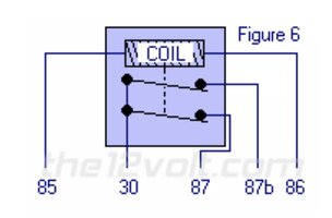
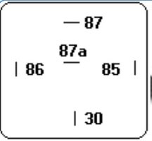
A double throw has 3 pins for the contact: common (C), normally open, and normally closed (NC, pin 87a). When the coil is not energized, you will have continuity between C/30 and NC/87a, but not C and NO/87. When energized, you'll get continuity between C and NO but not C and NC. You would use this in an either-or situation, as in either one or the other will be powered at all times.

You don't have to use the second 'throw' for it to function, so this can also be used as a SPST if you just ignore the center pin.
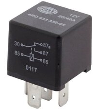
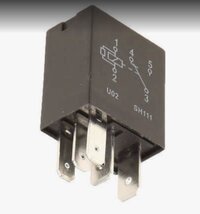
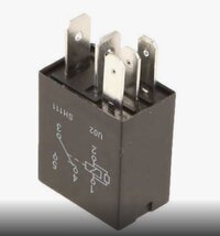
Hella, via Amazon

SinglePole,
DoubleThrow

(SPDT)

"PDC Style"


Screenshot 2024-01-01 at 10.38.44 PM.jpg
Another SPDT, but in a different style to fit in the PDC. Used for a few items like horn, ASD, etc.
 
Last edited:
  • Like
Reactions: Jack72 and Chris
A SPDT relay will work fine but it can easily be wired backwards so the fog light would shut off when the relay was energized... opposite of what you want. You want to wire the fog light via the relay's NO (Normally Open) contacts so the fog light goes on when the relay is energized.

Do you have a schematic drawing of the relay and its connections you can post here?
 
A relay has a coil, and contacts.

You supply voltage across the coil (pins 85 and 86), the contacts change state.

A typical SPST relay will have 2 pins for the contacts, which will be normally open (NO) which means the contacts will be open when the coil is not energized, and the contacts will close when coil is energized. These are pins 30 (common) and 87 (NO).

A double throw has 3 pins for the contact: common (C), normally open, and normally closed (NC, pin 87a). When the coil is not energized, you will have continuity between C/30 and NC/87a, but not C and NO/87. When energized, you'll get continuity between C and NO but not C and NC. You would use this in an either-or situation, as in either one or the other will be powered at all times.

Double pole (or 3+ pole) just means you have more sets of contacts that are controlled in unison by the energization of the coil.
 
  • Like
Reactions: SSTJ and Ocho
A relay has a coil, and contacts.

You supply voltage across the coil (pins 85 and 86), the contacts change state.

A typical SPST relay will have 2 pins for the contacts, which will be normally open (NO) which means the contacts will be open when the coil is not energized, and the contacts will close when coil is energized. These are pins 30 (common) and 87 (NO).

A double throw has 3 pins for the contact: common (C), normally open, and normally closed (NC, pin 87a). When the coil is not energized, you will have continuity between C/30 and NC/87a, but not C and NO/87. When energized, you'll get continuity between C and NO but not C and NC. You would use this in an either-or situation, as in either one or the other will be powered at all times.

Double pole (or 3+ pole) just means you have more sets of contacts that are controlled in unison by the energization of the coil.

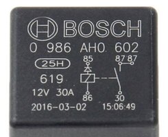
Here is a diagram on the side of the relay of the SPST relay with the 2 N/O contacts.most of these I have seen are a metal body of the relay. This one does not have a mounting tab but you can find a socket with a tab on it. These are nice for lights as you can run one wire from each lamp to the relay so no splice is needed.

IMG_0621.jpeg
 
  • Like
Reactions: freedom_in_4low
Here is a diagram on the side of the relay of the SPST relay with the 2 N/O contacts.most of these I have seen are a metal body of the relay. This one does not have a mounting tab but you can find a socket with a tab on it. These are nice for lights as you can run one wire from each lamp to the relay so no splice is needed.

View attachment 487289

Isn't this a SPDT?
 
Isn't this a SPDT?

The SPDT pin 30 connects to 87a when de energized and to 87 when energized.

On the metal case SPST relay 30 has no connection when de energized and connects to both pins 87 & 87 b when energized.]

IMG_0622.jpeg


IMG_0621.jpeg
 
The SPDT pin 30 connects to 87a when de energized and to 87 when energized.

On the metal case SPST relay 30 has no connection when de energized and connects to both pins 87 & 87 b when energized.

Got it, thanks. But I don't understand why the metal one would be called a SPST if it connects pin 30 to two pins (87 and 87b you say), whereas the SPST in my table only energizes one pin.
 
Here is a diagram on the side of the relay of the SPST relay with the 2 N/O contacts.most of these I have seen are a metal body of the relay. This one does not have a mounting tab but you can find a socket with a tab on it. These are nice for lights as you can run one wire from each lamp to the relay so no splice is needed.

View attachment 487289

We call those a Hella type headlight relay. They aren't, but that is where we first noticed them with the dual 87 terminals so you don't have to splice two wires to one output to run a pair of head lights, foglights, or similar.
 
We call those a Hella type headlight relay. They aren't, but that is where we first noticed them with the dual 87 terminals so you don't have to splice two wires to one output to run a pair of head lights, foglights, or similar.

Yes early German cars. VW, BMW. I have found them mostly metal case also but I don’t know now with the flood of cheap relays on the market.
 
The ones we use all have dual 87 terminals without the confusing 87b.

Yes, you are correct. I just used the “b” as that was the relay picture I pulled off the web. I not at home or I would of taken a picture of one.
 
  • Like
Reactions: SSTJ
Are you trying to wire up the fogs like stock? Folks have already covered the relay basics nicely so I won’t touch on that, however the fog setup Jeep used is a bit different. Since fogs are disabled when high beam turns on, Jeep uses a SPST NC relay (30 and 87 are always connected) and the high beam circuit is the trigger for the 86 pin (coil). This works out to where high beam triggers the relay which disables the fog circuit power that normally flows through that relay.

Now, I’ll have to check the FSMs to make sure that’s how all the different years work. I believe I saw this function in a 2006 FSM, so it might be different in other years, especially prior to 2001 when they used the MFS for everything.

I wasn’t sure if you’re maybe trying to understand the stock fog light circuit and how the relay interacts with it, hence my explanation.

Edit: earlier years were different. 1997 used 2 relays. Fog relay 2 is where parking lamp power normally flows through, and they used a normally closed relay there. High beam feed triggers that relay to go open when high beams are on.

When relay 2 is closed, that parking lamp power flows through relay 2 to the fog lamp switch. When fog switch is on, that parking lamp power from relay 2 flows through and goes to relay 1, where it triggers relay 1 as fog light power. Relay 1 is normally open, so fog light power triggers the relay to close, allowing battery power to go to the fog lights.

So on a 97 you have 2 SPST relays, one NC and one NO. I imagine they are both 4 pin from factory but keep could have used 5 pins, I’m not really sure without going to the pinouts.
 
Last edited:
  • Like
Reactions: freedom_in_4low